You may also like:
Timeless Tools: The Standard Modern Lathe
Racer Machinery International: Journey Through Generations
Ontario Made Expertise for the Next Generation
A CNC (Computer Numerical Control) machine is a marvel of modern engineering, capable of transforming raw materials into precise components with unmatched efficiency. At the heart of these machines lies a complex interplay of components, each playing a vital role in the manufacturing process.
The Seven Pillars of CNC Machining
-
Machine Control Unit (MCU): The MCU is the brains of the operation, interpreting G-code instructions and translating them into electrical signals that control the machine’s movement. It’s the central hub that ensures precision and accuracy in every operation.
-
Drive System: The drive system, comprising motors, gears, and belts, is responsible for powering the machine’s movements. It ensures that the cutting tool and workpiece are positioned with utmost precision, enabling intricate and complex machining tasks.
-
Machine Tool: The machine tool, typically a spindle holding various cutting tools, is the physical implement that shapes and removes material. Its movement, controlled by the MCU and drive system, determines the final shape and dimensions of the workpiece.
-
Feedback System: The feedback system, equipped with sensors like encoders and linear scales, constantly monitors the machine’s position and movement. It provides real-time data to the MCU, allowing for instant adjustments to maintain accuracy and prevent errors.
-
Bed and Table: The bed provides a sturdy base for the entire machine, while the table serves as the platform for the workpiece. The table can be moved along different axes, enabling precise positioning of the material relative to the cutting tool.
-
Cooling System: The cooling system plays a crucial role in maintaining optimal operating conditions. It dissipates heat generated during the machining process, preventing overheating and ensuring the longevity of the machine and cutting tools.
-
Input Devices: Input devices, such as computers, keyboards, and USB ports, allow operators to input G-code programs and control the machine’s operations.
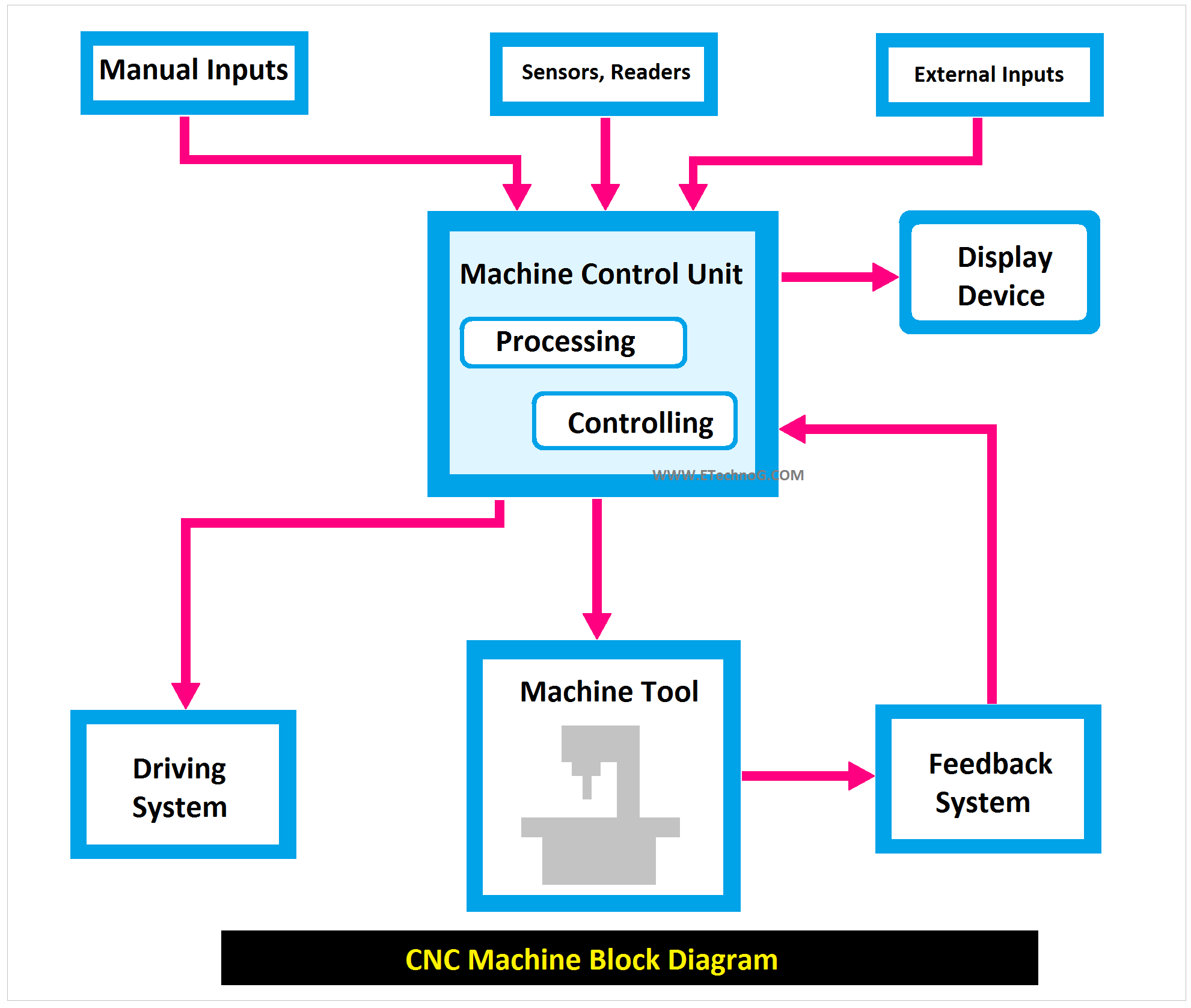
Understanding the CNC Block Diagram
A CNC block diagram provides a visual representation of how these components interact. It typically includes:
-
- Input Block: Represents the devices used to input G-code programs.
- MCU Block: The central processing unit that interprets G-code and controls machine movements.
- Drive System Block: Includes motors, gears, and belts that power the machine’s motion.
- Machine Tool Block: Represents the cutting tool or spindle that performs machining operations.
- Feedback System Block: Monitors machine position and movement, providing real-time data to the MCU.
- Bed and Table Block: Represents the foundation and workspace of the machine.
- Cooling System Block: Indicates the system that manages heat and lubrication.
By understanding the intricate interplay of these components, one can appreciate the remarkable capabilities of CNC machines. From simple to complex, CNC technology continues to revolutionize manufacturing processes, driving innovation and efficiency.
